Loading...
Loading...
Loading...
Loading...
Loading...
Loading...
Loading...
Loading...
Loading...
Loading...
Loading...
Loading...
Loading...
Loading...
Loading...
Loading...
Loading...
Loading...
Loading...
Loading...
Loading...
Loading...
Loading...
Loading...
Loading...
Loading...
Loading...
Loading...
Loading...
Loading...
Loading...
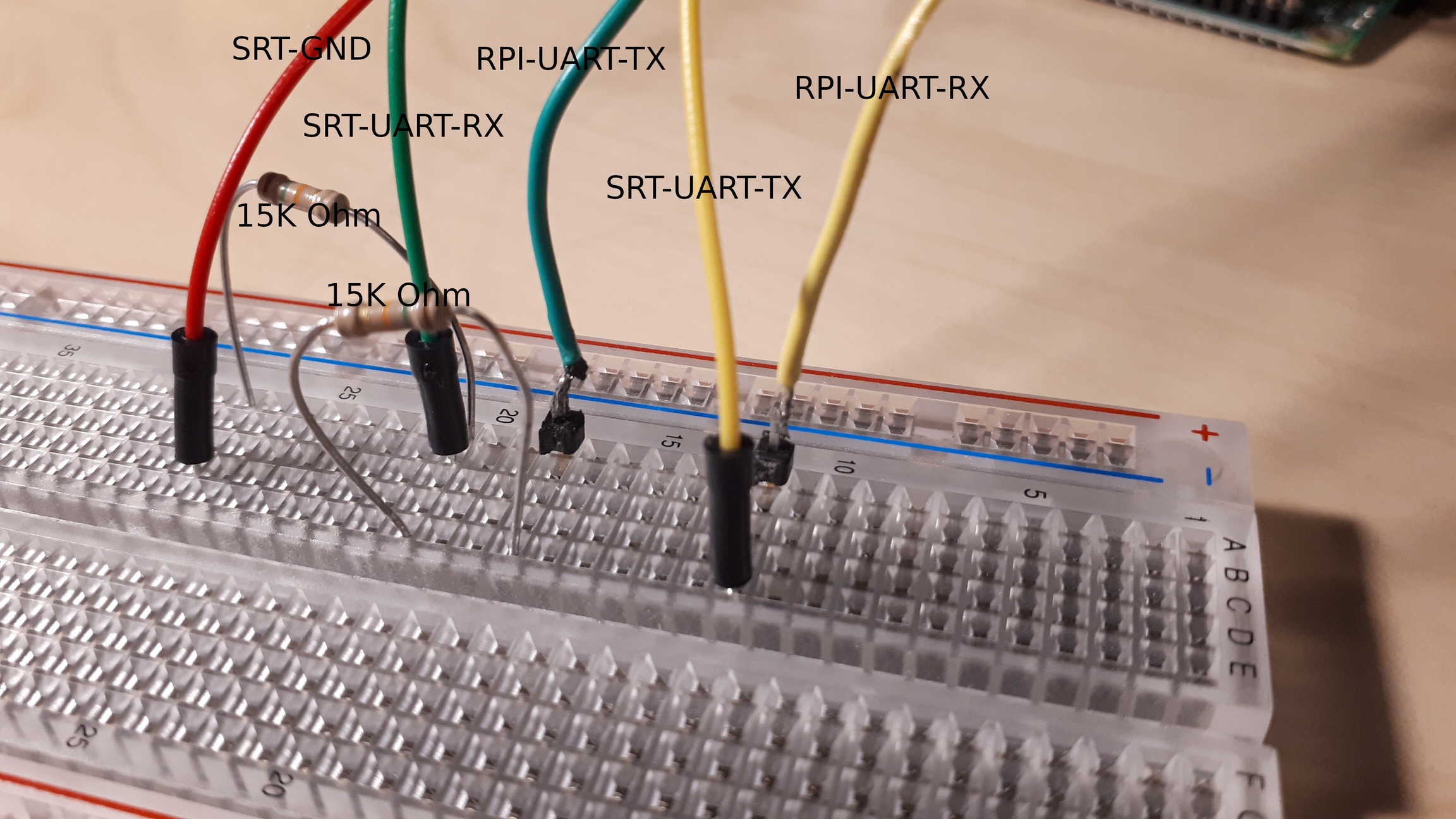
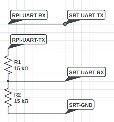
Connect 3.3/5V UART hardware to a 1.8V device using a voltage divider
We recommend buying suitable 1.8V equipment
Use a voltage divider to get TX 3.3V / 5V down to 1.8V
3.3V: Z1 = 20k; Z2 = 20k
5.0V: z1 = 20k; Z2 = 47k
These values should be safe even if the resistors vary by 5%
Test the output Voltage before you send data to 1.8V ports
Connection of Z2 to GND is very important. If it has a bad connection Vout can get close to Vin
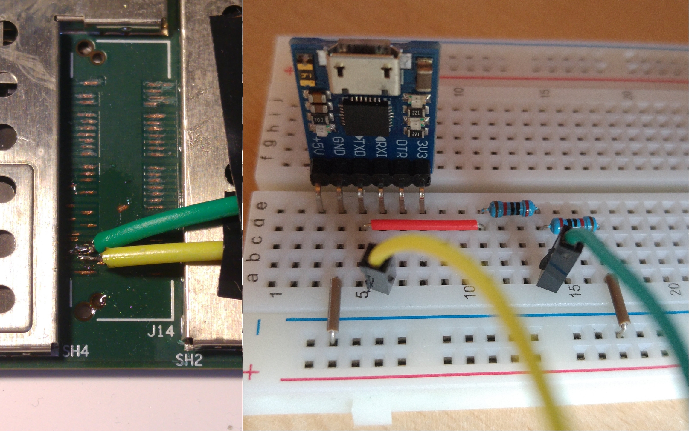
You need to have a common GND. The easiest method is connecting UART-GND and SRT-GND.
See Raspberry Pi UART Setup for further on information on how to setup your RPI.
Raspberry Pi's use 3.3V UART. Surface RT only uses 1.8V.
Raspberry Pi can receive 1.8V signals without a problem. But the Surface doesn't want to receive a 3.3V Signal. Therefore we need a levelshifter. A simple and cheap solution is to use a voltage divider, as shown above.
Hardware used in the SurfaceRT
The Surface RT was launched in October 2012
It contains a TEGRA 3 (aka Tegra30 processor), and 2G of ram.
https://support.microsoft.com/en-us/help/4037671/surface-surface-rt-specifications See the IC page for further information
Large image of PCB https://d3nevzfk7ii3be.cloudfront.net/igi/kJPLhr5dsLNwXTAb Teardown with photos of board and setup https://www.techrepublic.com/pictures/cracking-open-the-microsoft-surface-with-windows-rt/
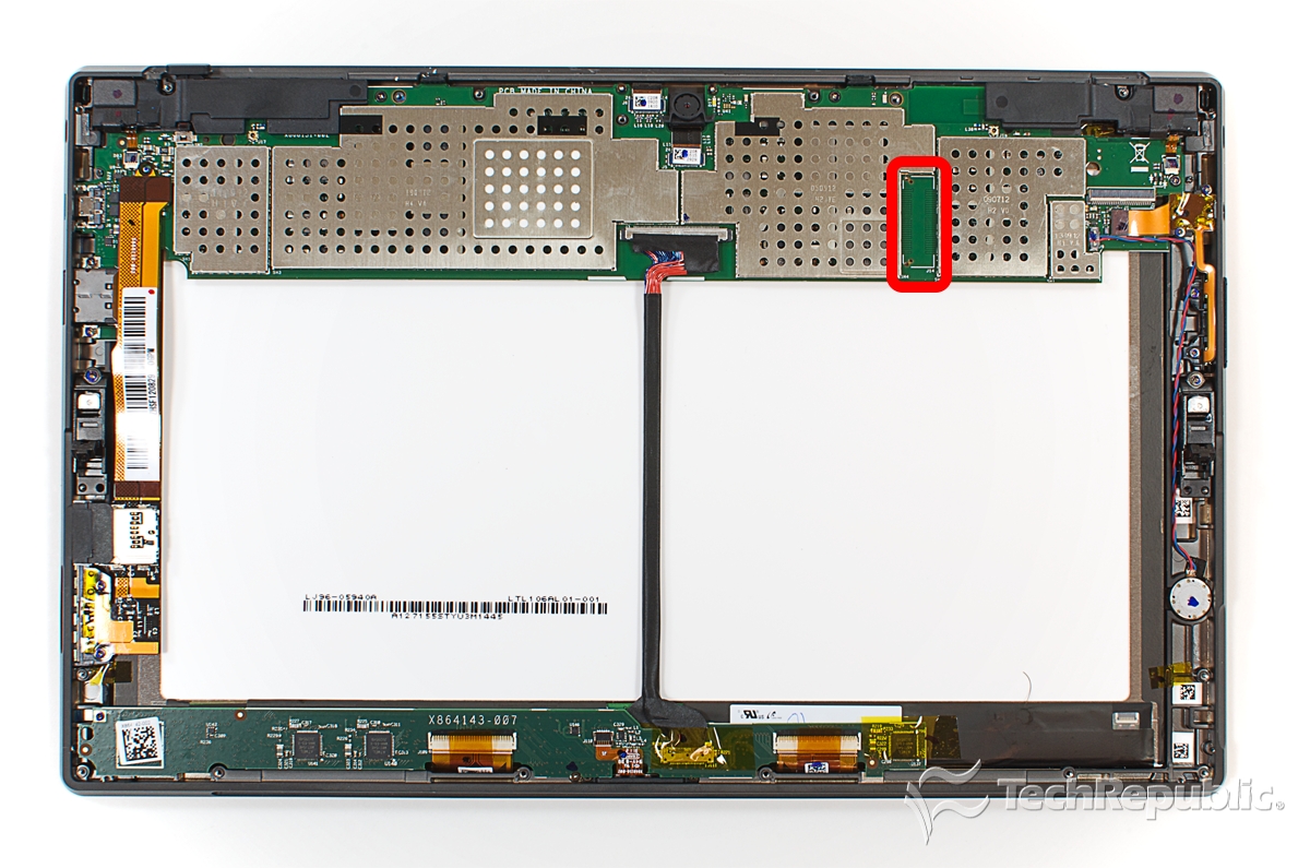
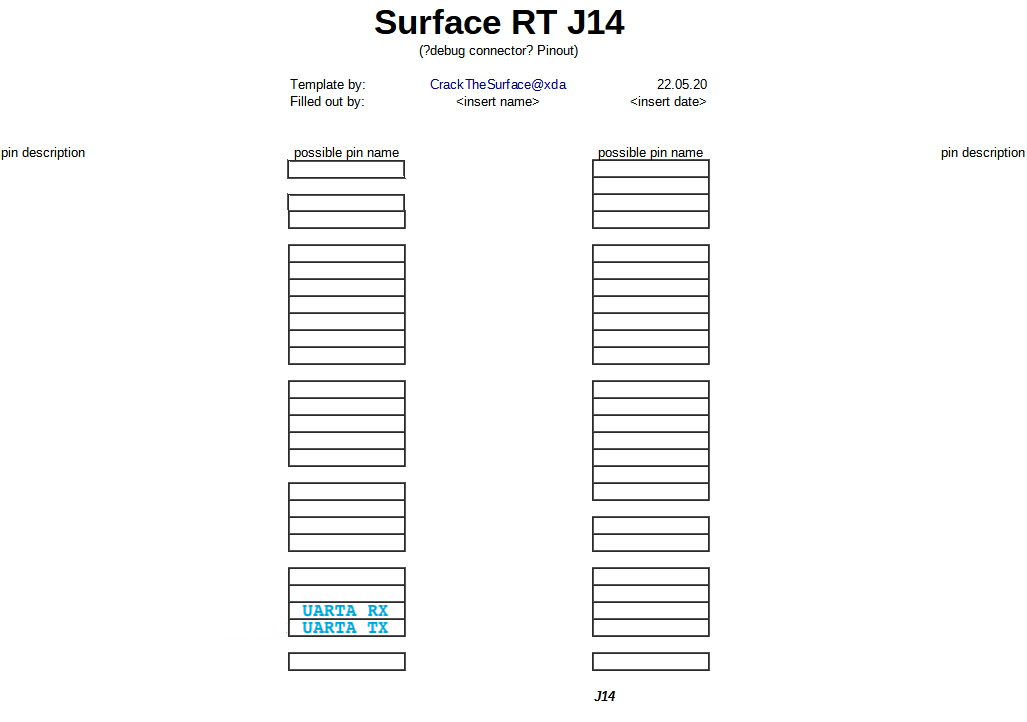
Surface RT UART-A access
To properly debug Linux a serial console is needed. Tegra30 has 5 hardware UART ports. They are called UART-A/B/C/D/E
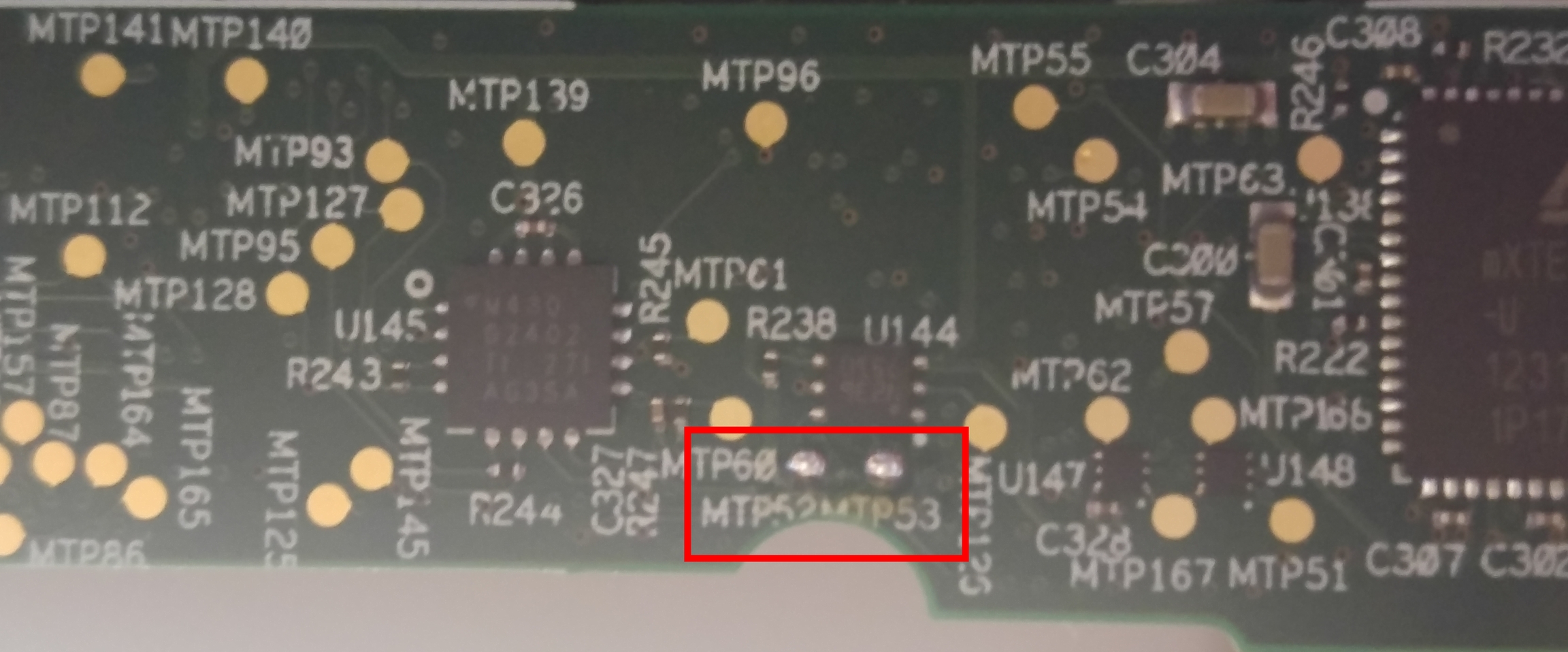
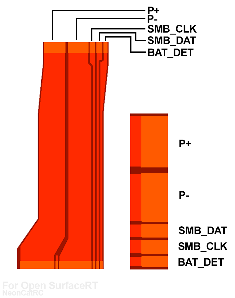
Below you can see where you can find the UARTA TX, RX pad.
GND from Surface RT must be connected to GND of your UART adapter. If you use fusee gelee your devices are connected via USB-GND. If not you must find suitable GND on sRT.
To use UART you need i.e. a usb-uart adapter, a raspberry pi, arduino, etc... A "silicon labs cp210x usb to uart bridge" was used in testing. This is a 3V3 chip which is 5V tolerant. Receiving a 1.8V signal works fine. But sending 3.3V to a 1.8V input is dangerous.
Be careful when you remove the soldermask (green layer covering the copper). You dont want to cut the trace or short it to any trace below! These pads are very tiny, soldering them is hard without skill and good equipment. It's recommened to use small solid core wire. if you use stranded wire (like i did) only use 2-3 strands. Cut off the rest. Secure your wires with good tape.
We took an oscilloscope and checked that there isn't a pin which provides more than 5V (max of uart adapter).
After this we probed every pin with a usb uart adapter and minicom. After a few seconds we found the corresponding TX-pad.
Top left: dmesg -Tw show that sRT is booted in APX mode. Also shows if it gets disconnected.
Bottom left: Fusee Gelee launcher with payload and ProductID (see dmesg)
Top right: Minicom output
Bottom right: Fusee gelee payload source code
At this time we got uboot booting. We got output from uboot over UART-A-TX so we only had to bring an TX signal from pc to the RX pad on surfaceRT.
One educated guess later we found RX next to TX.
Uboot told us that 1 isn't a valid command. after this we tried help and and got a solid answer
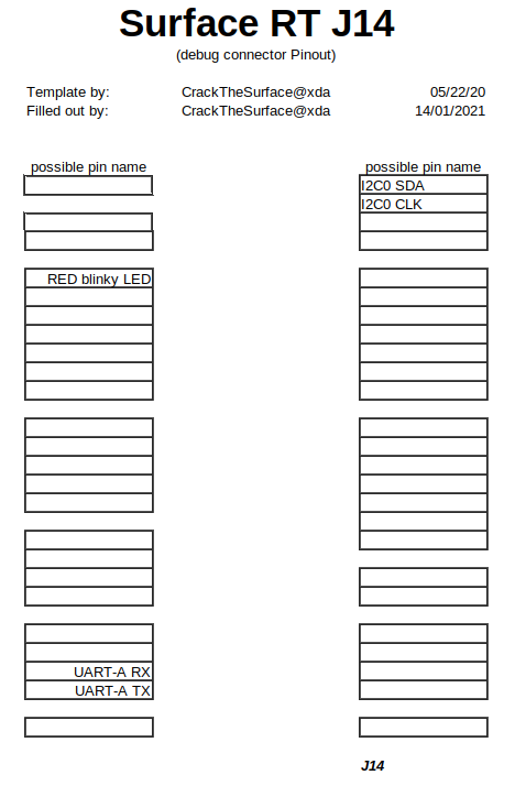
UART-A is on the ULPI data pins on the SoC ()
UART-A TX can be found on . It transmits data at 1.8V UART-A RX can be found on . It receives data at 1.8V
A which initializes UART-A with Baud: 115200, Bits: 8, Stopbits: 1, Parity:None
was used to find it.
After initialisation its spams data to the transmit buffer.
Release Date
October 2012
Display
Screen: 10.6" 1366x768 16:9
Display - LTL106AL01-002 (1368x768) LVDS Backlight WLED 12V; Screen Input Voltage: 3.3V
SoC
Nvidia Tegra 3 T30
CPU
Quad core Cortex-A9 @ 1.3 GHz
Core architecture
ARMv7/ARMhf 32-bit
RAM
Micron 2RE22 D9QBJ 2 GB DDR3 SDRAM
Storage
- Samsung KLMBG4GE4A NAND Flash
- 64GB or 32GB capacity
Camera
1.2MP Rear and 1.2MP Front
Operating System
Windows RT 8.0 (Upgradable to Windows RT 8.1)
Battery
Samsung Li-ion: 7.4V at a 31.5 Wh
Setup your Raspberry Pi to communicate with the SurfaceRT.
To enable the UART on your Raspberry Pi to be used as host you need to configure it:
sudo raspi-config
Go to 5 - interfacing options
Go to P6 - serial
Would you like a login shell to be accessible over serial? Answer: 'No'
Would you like the serial port hardware to be enabled? Answer: 'Yes'
Reboot your Raspberry Pi.
See Raspberry Pi for information on how to physically connect your RPI and your SRT.
To establish a UART-Connection to the Surface RT use
RPI2: minicom -b 115200 -D /dev/ttyAMA0
RPI_Zero minicom -b 115200 -D /dev/ttyS0
To escape from minicom use STRG+A and then X.
Further information: https://www.raspberrypi.org/documentation/configuration/uart.md
if we take a look at the ACPI table we see several GpioIO functions.
Identifying the Volume keys is easy. We can dump the GPIO-Controller from UEFI shell while a volume key is pressed or released.
We see that we changed something with a button press. Nice! We see that 1 Byte has changed from 0xC0 to 0x80 at address 0x438 In binary: 1100 0000 -> 1000 0000 => Bit 6 has changed.
Lets take a look at 0x438
Now we know that we changed Pin6 in Port S => Vol-Down is connected to PS6
S is the 19th letter of the Alphabet counting from 1 (A=1, B=2, C=3,...) S is the 18th letter of the Alphabet counting from 0 (A=0, B=1, C=2,...) TRM tells us that every port has 8 pins. So lets multiply 18 by 8 which equals 144 and add our PinOffset: 6 144+6 = 150 Convert 150 from dec to hex: 0x96
We can match the 4 GPIOs to the SurfaceHomeButtonDriver. We can see that Windows knows 4 Interrupts. At the moment we dont know how to map the WindowsIRQ to ACPI-IRQ or LinuxIRQ
Linux enumerates GPIO in the same way as ACPI:
portNumber * 8 + pinOffset (+ gpioControllerOffset)
(gpioControllerOffset is 0 on tegra 3)
We know that we deal with:
Vol-Down: 0x96 / 150d
Vol-Up:   0x97 / 151d
We guess 0x97 because it is a normal shared interrupt.
The other 2 interrupts are WakeUp Interrupts which should belong to the Power/WindowsButton
include libgpiod in your root filesystem
type gpiomon <BUS> <Gpio-Number>
Press the button a few times you should see the gpio chaning in realtime
first we must set the pins to GPIO mode. Tegra standard is SFIO mode. 0x6000 d000 is the GPIO Controller base 0x0000 0408 is PortS CNF register. We want to set pin 6/7 to GPIO mode -> 0b1100 0000 -> 0xC0
we can write memory with devmem
devmem 0x6000d408 8 0xC0
Now the GPIO Controller treats PS6/7 as GPIO
cd /sys/class/gpio
ls ./ should show export, gpiochip0, unexport
gpiochip0 is the gpio controller; 0 tells the offset
we can export a pin to userspace
echo 150 > export
echo 151 > export
Now we can use PS6/7
check the direction with
cat gpio150/direction
it should show "in"
but you can set it with echo in > gpio150/direction
Now we can read the value
cat gpio150/value
this should return 1
if you press VOL-Down it should return 0
This tells us that the pin is pulled up and active_low.
Now remove the gpio from userspace that it can be used by drivers again
echo 150 > unexport
echo 151 > unexport
Letter number
dec range start
hex range start
Letter
0
0
0x00
A
1
8
0x08
B
2
16
0x10
C
3
24
0x18
D
4
32
0x20
E
5
40
0x28
F
6
48
0x30
G
7
56
0x38
H
8
64
0x40
I
9
72
0x48
J
10
80
0x50
K
11
88
0x58
L
12
96
0x60
M
13
104
0x68
N
14
112
0x70
O
15
120
0x78
P
16
128
0x80
Q
17
136
0x88
R
18
144
0x90
S
19
152
0x98
T
20
160
0xA0
U
21
168
0xA8
V
22
176
0xB0
W
23
184
0xB8
X
24
192
0xC0
Y
25
200
0xC8
Z
26
208
0xD0
AA
27
216
0xD8
BB
28
224
0xE0
CC
29
232
0xE8
DD
30
240
0xF0
EE
32/64GB internal eMMC
HID over I2C
Address: 0x28
Bus speed: 400kHz
HID_Descriptor: 0x0001
ACPI Device: SNMU
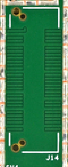
I2C Bus
Access to I2C Bus 0 can be found on J14.
https://en.wikipedia.org/wiki/Extended_Display_Identification_Data
ICs which are used in the Surface RT
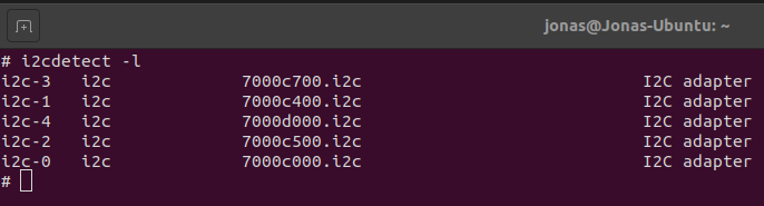
I2C Devices which can be found in the Surface RT
i2c-0 i2c 7000c000.i2c I2C adapter - LVDS DDC (according to cardhu devicetree) - access on J14 i2c-1 i2c 7000c400.i2c I2C adapter - daughter board (touch controller; touch/typeCover) - access MAYBE on DaughterBoard Testpoints i2c-2 i2c 7000c500.i2c I2C adapter - nothing - dont care i2c-3 i2c 7000c700.i2c I2C adapter - HDMI DDC - Via HDMI-port i2c-4 i2c 7000d000.i2c I2C adapter - PMIC - not found :(
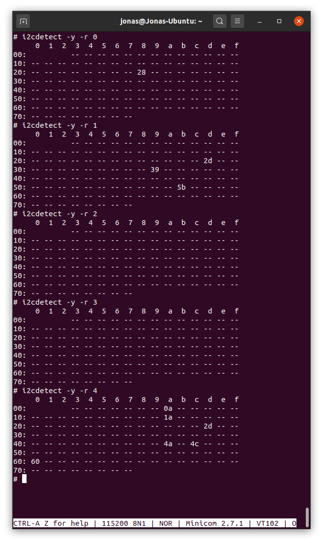
I2C addresses on Bus - 0: 0x00; 0x28 - 1: 0x2D; 0x39; 0x5B - 2: - 3: depends on HDMI display - 4: 0x0A; 0x1A; 0x2D; 0x4A; 0x4C; 0x60
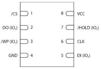
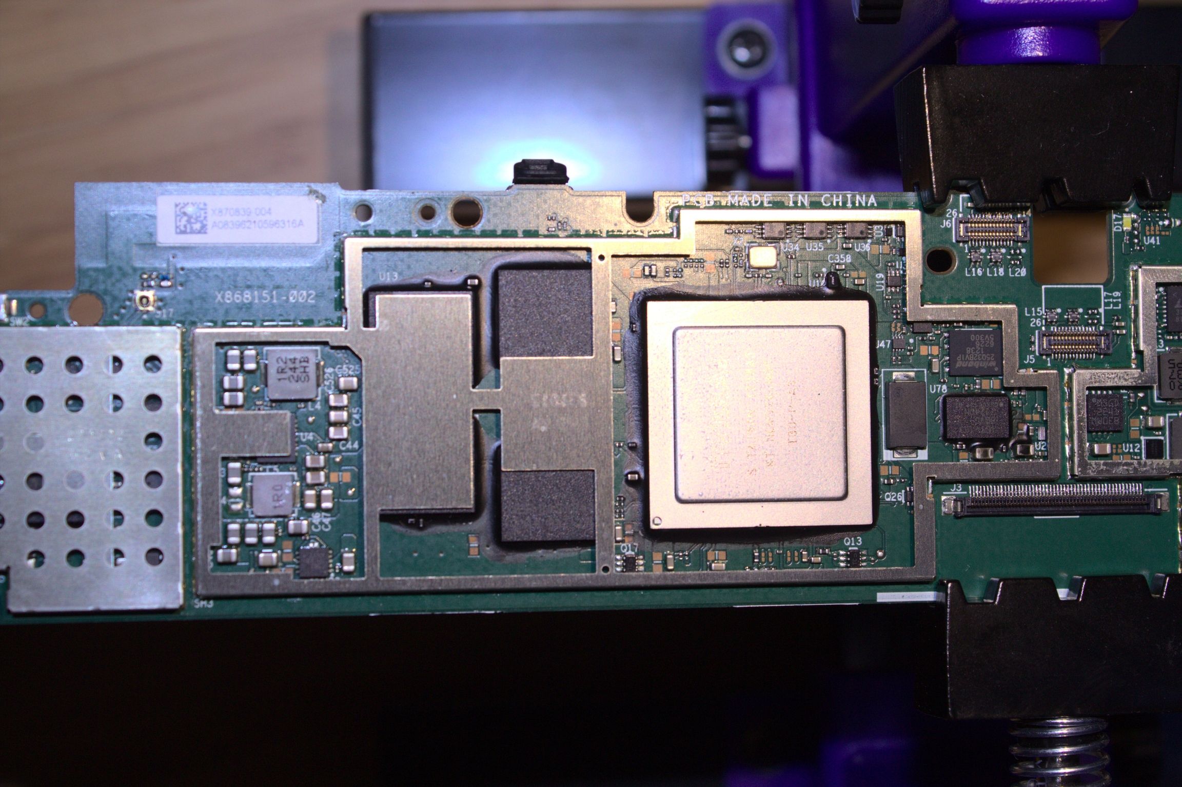
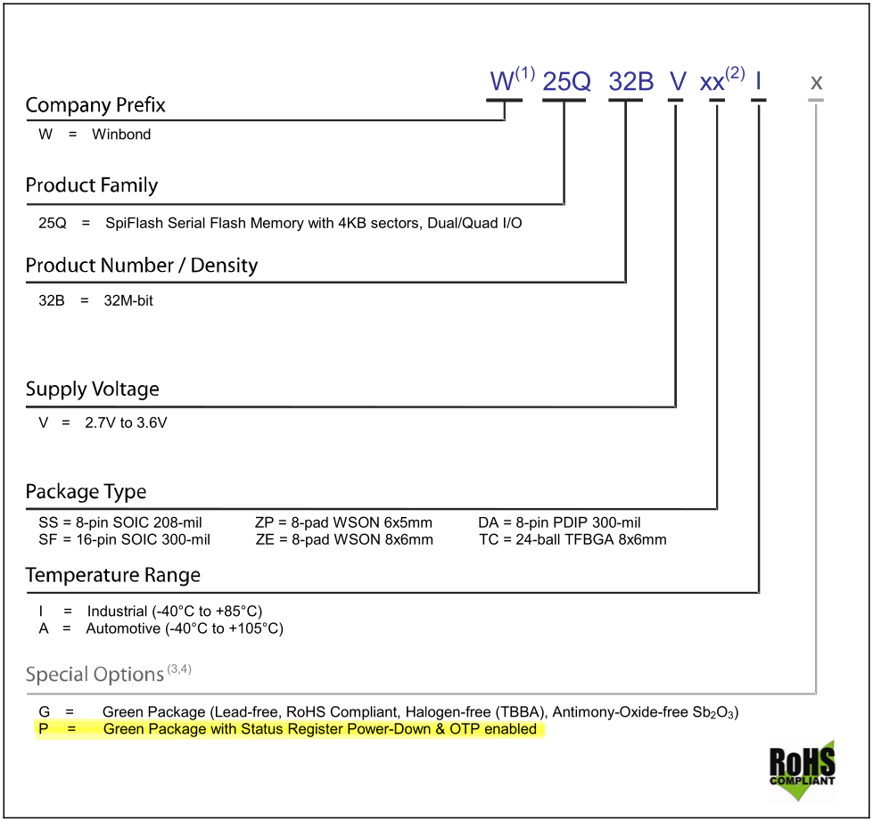
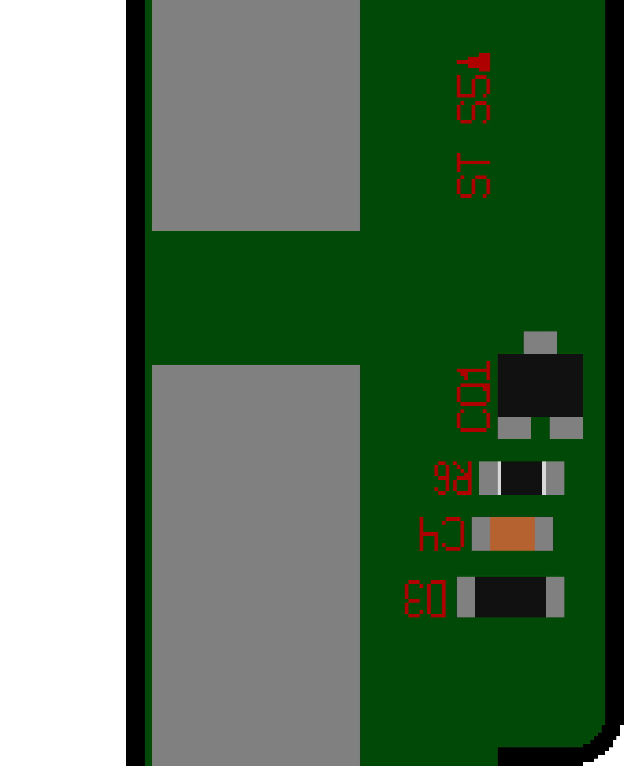
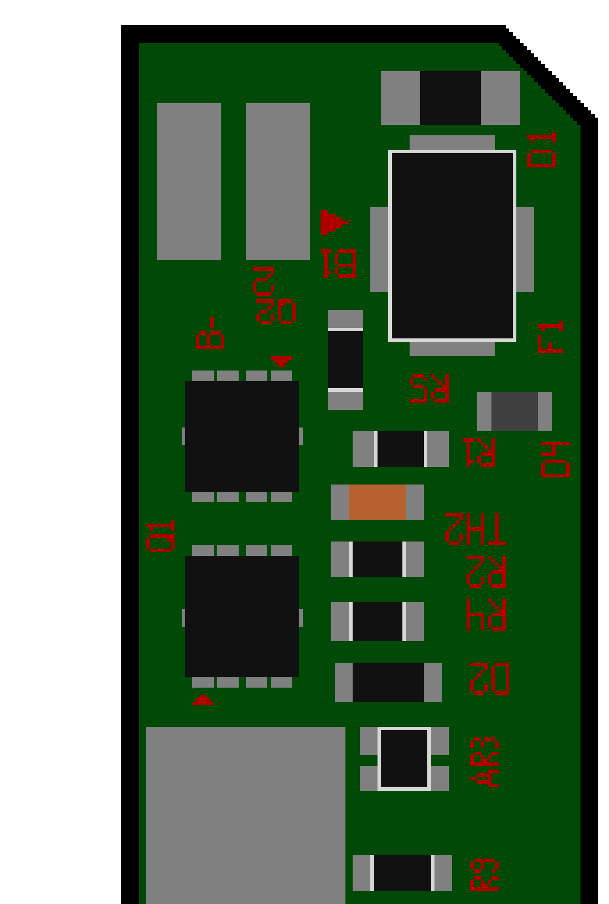
Boot loader for the RT1 is written on a Winbond W25Q32VIP. This is a 32MBit (4K Byte) SPI flash chip that operates in Single mode and comes in an 8 pin WSON 6X5-MM package. Its contents are locked in because of the P variation in its name that specifies the OTP (Write Once) feature in the chip. This means the contents can't be replaced. We can however replace the entire chip.
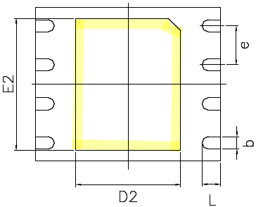
Below is the pinout for Single mode operation of the chip.
Before starting it is recommended to dump the contents of the chip as it contains unique configuration aspects for the device. Check the firmware section on how to do this
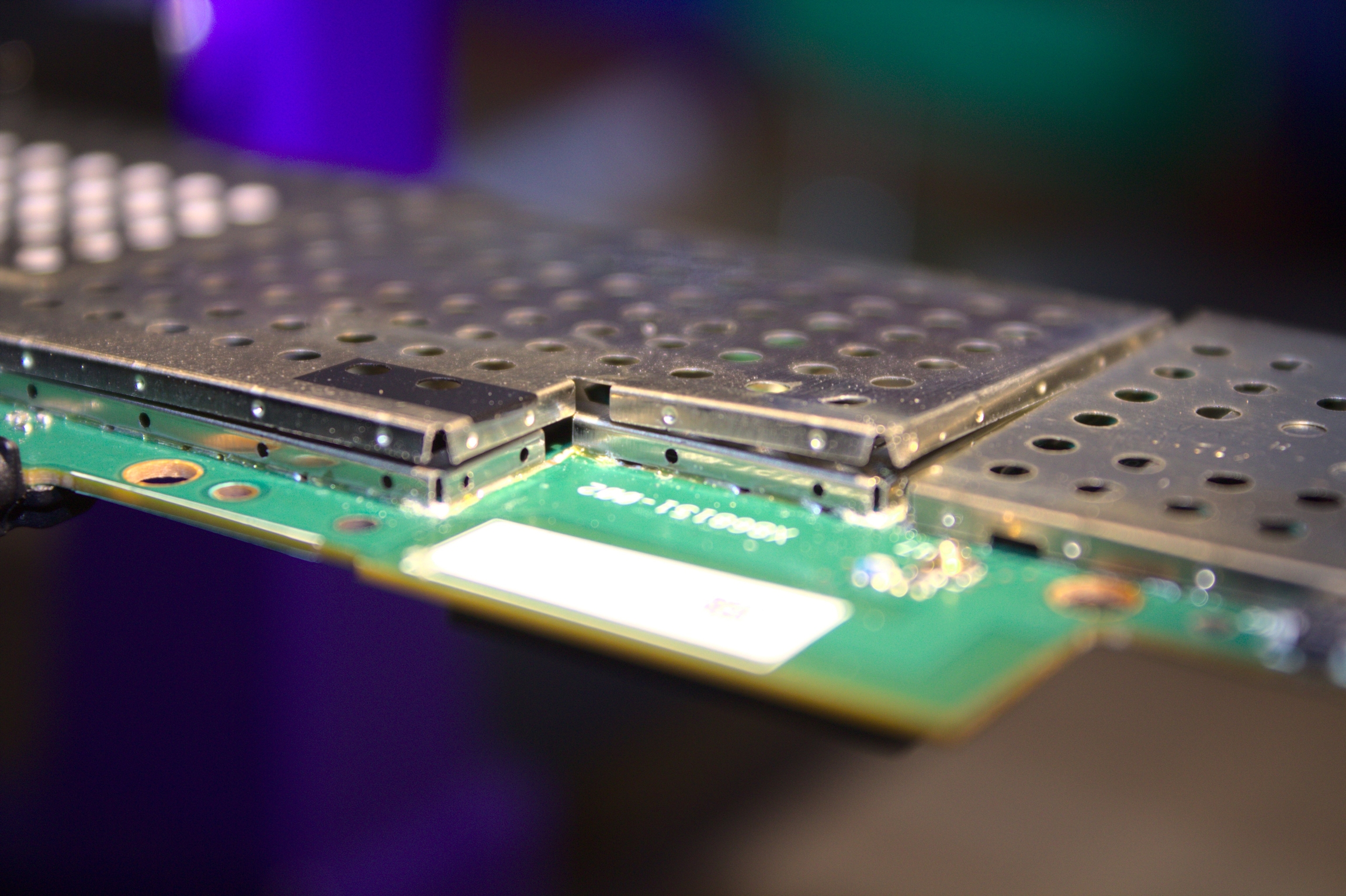
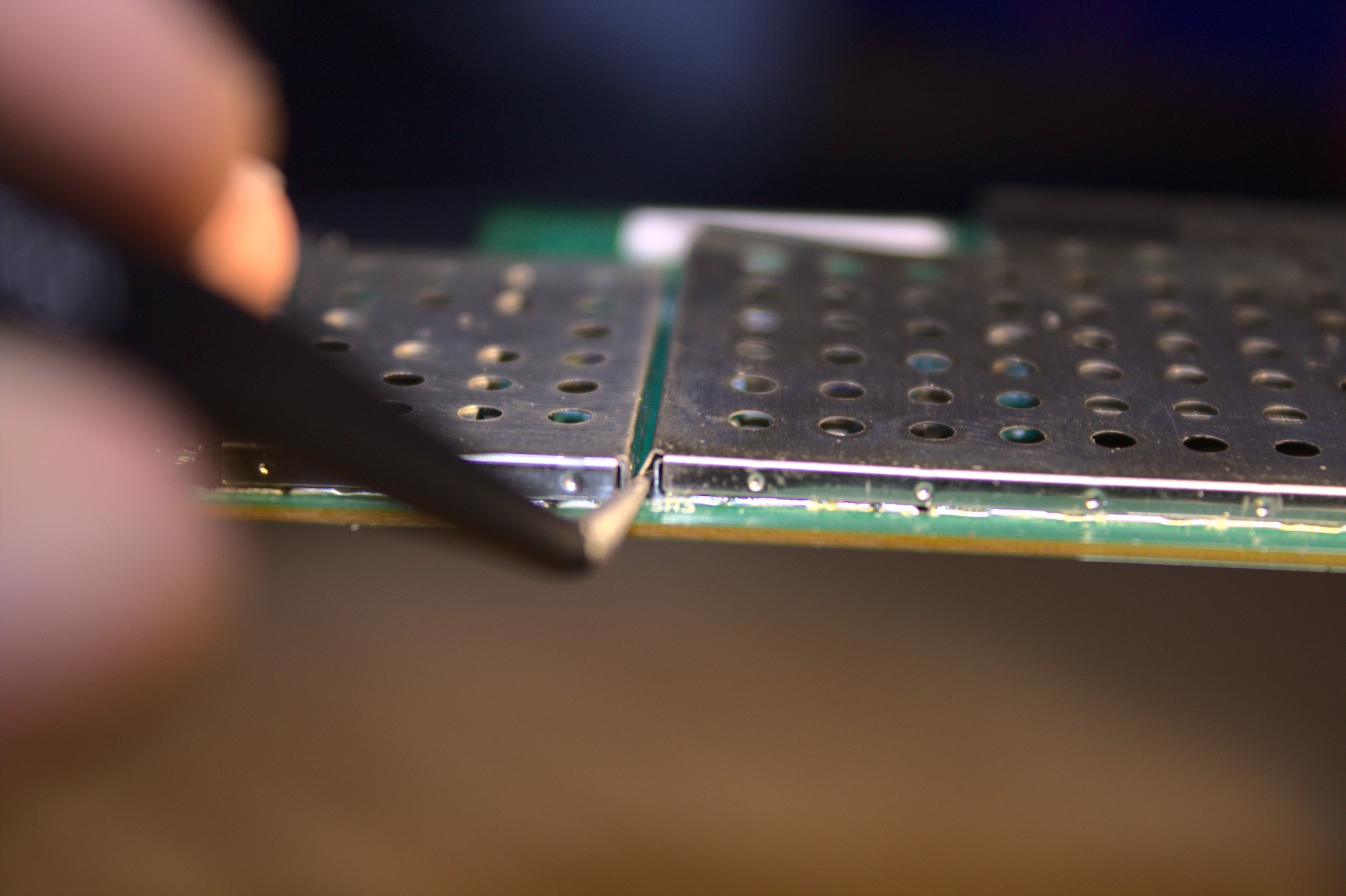
Replacing the chip is not to be taken lightly. It requires a hot air station to remove as it is a surface mounted package with a big ground pane in the center. Beside this there are multiple components close to the chip that need to stay in place.
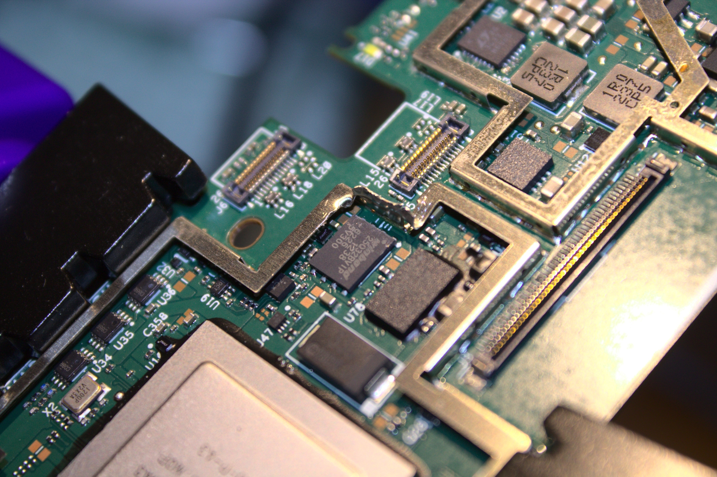
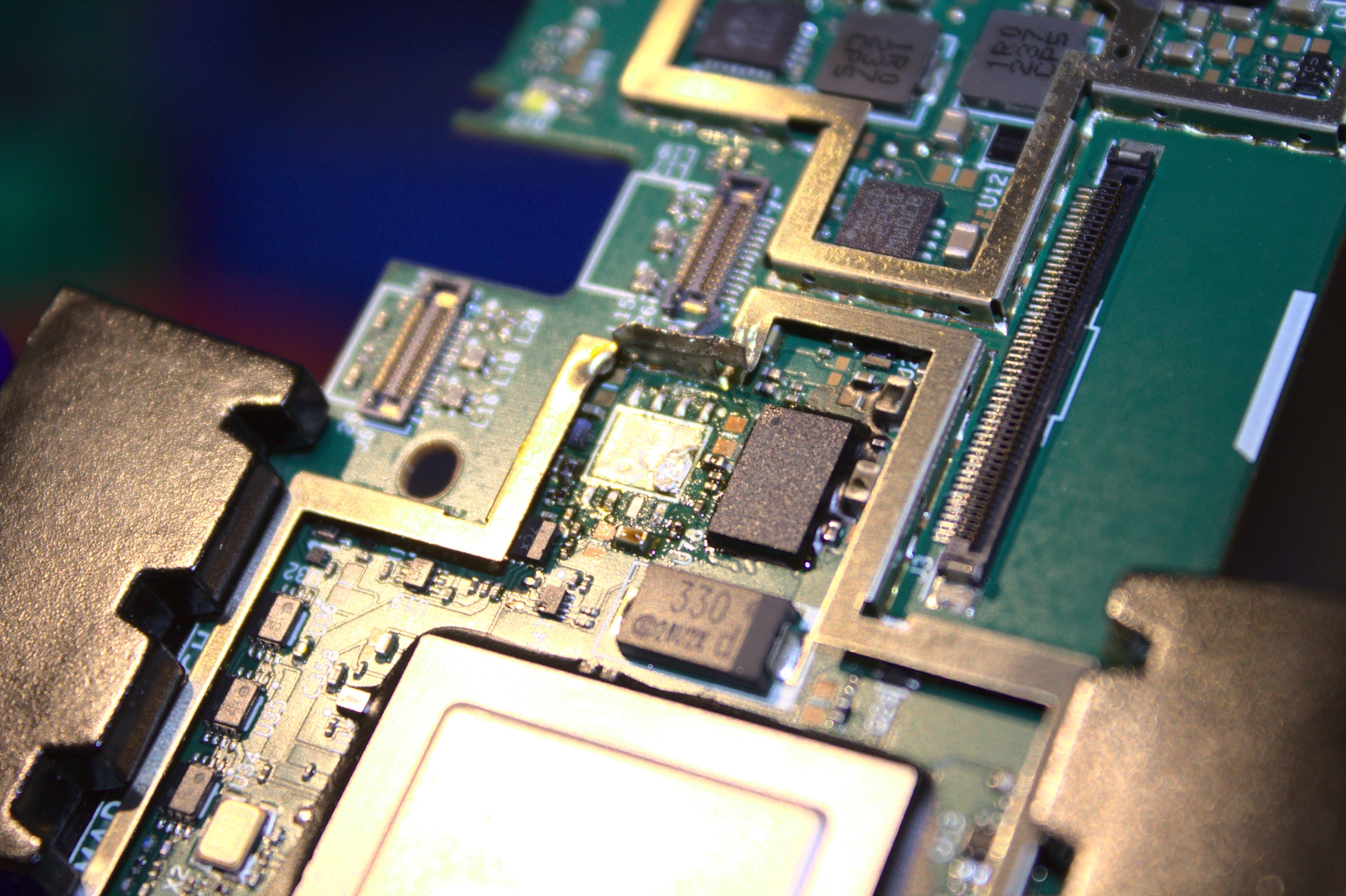
Begin by the shield covering the SOC, Memory and flash chips. This will come of very easily with little force. Take your time doing this.
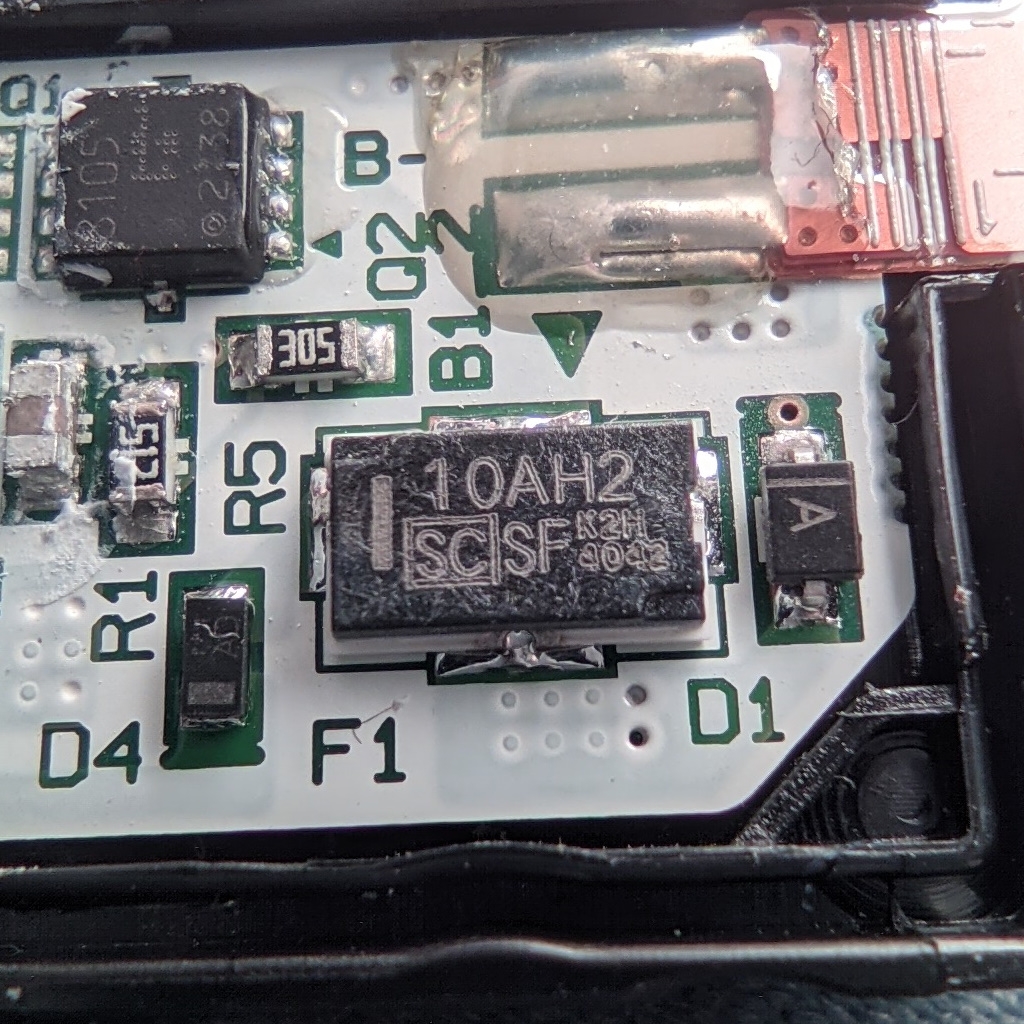
Once removed we have an overview over the most important components
To make the flash chip better accessible, the metal that held the shield in place can be bent back slightly. To help the desoldering the back of the PCB should be pre-heated at a low temp before starting work on the front. This will help with removing the chip and its big ground pane. Then start heating the flash chip itself at a low flow to not disturb the components around it. Make sure to heat it properly as forcing the chip off will break the pads on the PCB.
Technical information about Type/Touch Covers for Surface RT/2
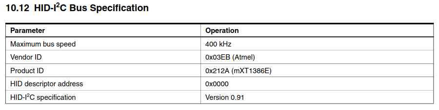
HID over I2C
Address: 0x00
Bus speed: 400kHz
HID_Descriptor: 0x0041
ACPI Device: SNMU
Power:
Bridge IC: PMIC.REG1: 1.8V
tCover Power: PMIC.REG3: 2.8V
HID Interrupt: O5 Hotplug Interrupt: S0
The tCover I2C address is 0x00. This address is reserved for general call.
Linux doesn't allow I2C Slaves to use this address therefore the I2C driver must be patched to allow 0x00 as valid Slave address.
i2c-hotplug-gpio is a grate driver and doesn't work in mainline.
IC
Datasheet(s)
Cypress Semiconductor CY8C20466A
TI MSP430G2402 Microcontroller
belongs to "ATMEL: mXT1386E - TouchController"
Atmel UC3L microprocessor
Pin
Name
I/O
Function
1
/CS
I
Chip Select Input
2
DO
O
Data Output
3
/WP
I
Write Protect Input
4
GND
Ground
5
DI
I
Data Input
6
CLK
I
Serial Clock Input
7
/HOLD
I
Hold Input
8
VCC
Power Supply (3.3V)
Cover
Generation
VendorID / hex
ProductID / hex
Touch
1
045E
079A
Type
1
045E
079C
Touch
2
045E
07A7
Type
2
045E
07A9
Power
1
045E - tbc
07DA - tbc
related to Surface Home Buttone Driver
Cypress touch sensor config?? MSP430??
Normal I2c
Address: 0x0A
Surface RT uses the Embedded Controller Topology. The controller is located at 0xa.
That means that there must be an IC somewhere which interacts with the Charger and the Fuelgauge and provide an interface to both of them to the SoC.
The Charger and the Fuelgauge are exposed through 0xa which provides an ACPI interface.
The ACPI BAT0 device deals with the Fuelgauge.
The ACPI ADP0 device deals with the Charger.
The ACPI methods like _BIX, _BTS, ... provide all the necessary information about the battery and the charger.
They can be decrypted by reading the ACPI Spec p. 492 10.2 Control Method Batteries
https://wiki.ubuntu.com/Kernel/Reference/Battery "(Control Method) Batteries and ACPI are tied together in quite a complex way. Generally, the battery state information is transmitted over a SMBUS bus to the embedded controller, a.k.a. EC, which in turn interfaces to the OS via ACPI methods. These methods can interrogate the embedded controller for battery state information ..."
Battery <-- EC <--> BIOS ACPI Methods <--> OS
Since there is no ACPI implementation for ARM32 and we need to replace the ACPI Methods with a custom driver. all Necessary information can be found in the SSDT0000 ACPI table
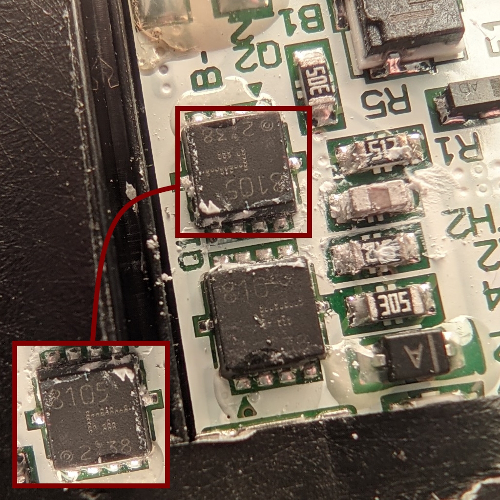
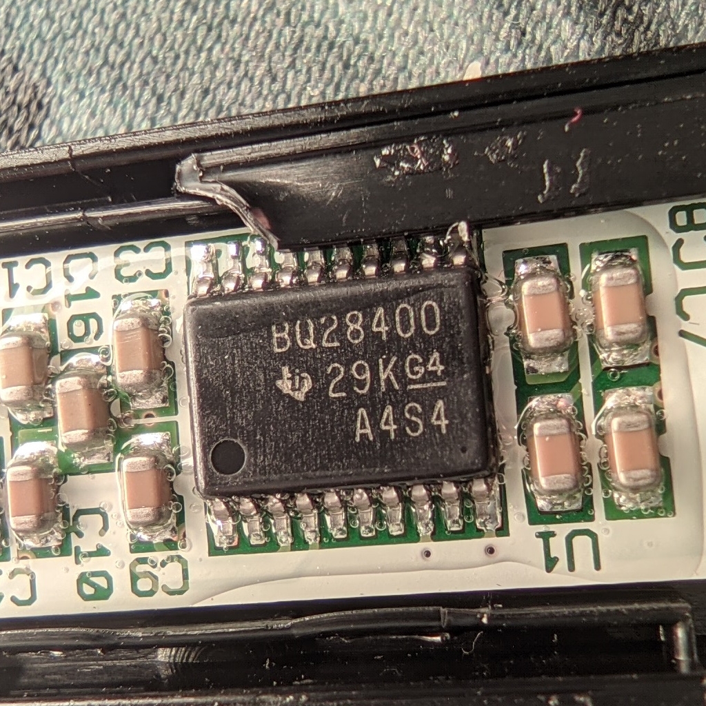
The Embedded Controller directly interacts with the Charger and the Fuelgauge.
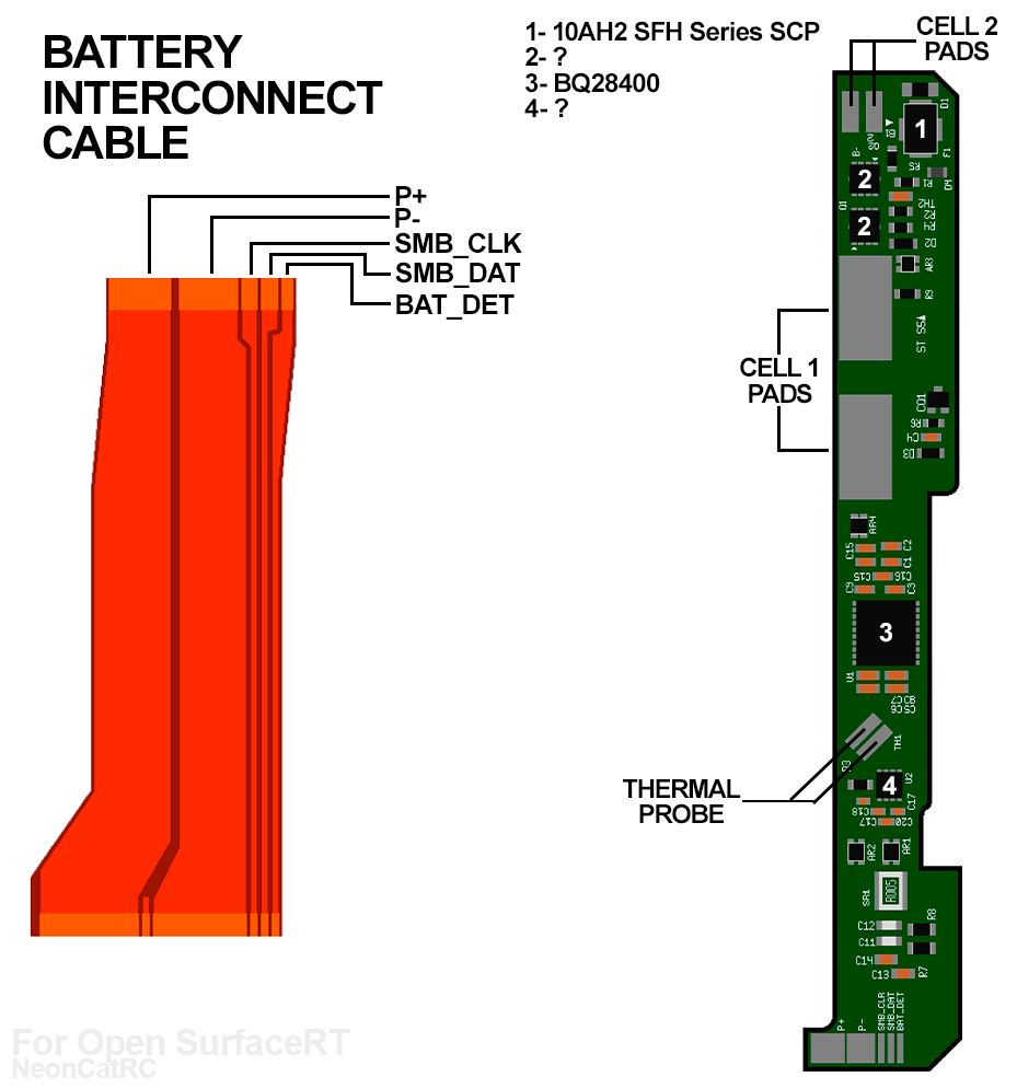
BQ28400
https://www.ti.com/lit/ug/sluu431/sluu431.pdf https://www.ti.com/lit/ds/symlink/bq28400.pdf?ts=1625607689401&ref_url=https%253A%252F%252Fwww.ti.com%252Fproduct%252FBQ28400
BQ24725A
The Embedded Controller topology prevents the use of SmartBatterySystem (SBS) and requires an ACPI or custom driver. ACPI isn't (fully) implemented on ARM32 therefore we need a custom driver which resembels the ACPI methods.
https://uefi.org/sites/default/files/resources/ACPI_5_0_Errata_B.pdf
HID over I2C
Address: 0x5b
Bus speed: 400kHz
HID_Descriptor: 0x0000
ACPI Device: TOUA
http://ww1.microchip.com/downloads/en/DeviceDoc/mXT1386E_2v4_Datasheet_BX.pdf
ACPI tells that the device TOUA uses I2C-2@400kHz with an address of 0x5b
HID Interrupt: K2
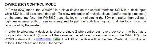
Normal I2C
Address: 0x1A
https://statics.cirrus.com/pubs/proDatasheet/WM8962_Rev4.4.pdf
The I2C address seems to be 0x34 but that's the 8 Bit address. Shift the address 1 to the right (>>1) and you get 0x1A as 7Bit address
Wolfson WM7220 Microphones
Integrated Device Technology V103 LVDS encoder - IDTV103
Tegra 3 only supports a parallel interface or SPI LCD, DVI, an HDMI HDTV, RGB monitor or a MIPI DSI LCD.
Surface RT uses a LVDS Display. Therefore an translator is needed.
They used a Integrated Device Technology V103 LVDS encoder https://datasheetspdf.com/pdf-file/696938/IntegratedDeviceTechnology/V103/1
The converter is transparent to the SoC and does its job without any configuration. It only needs power and the PowerDown pin set to LOW
B2 - power down
If we set this pin to LOW from UEFI Shell new information can't be send from the SoC to the display. In this case the image fades out.
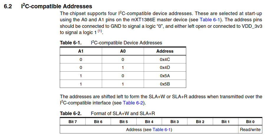
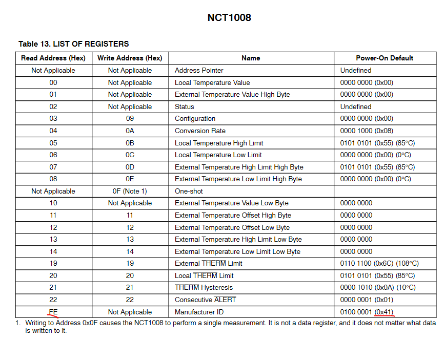
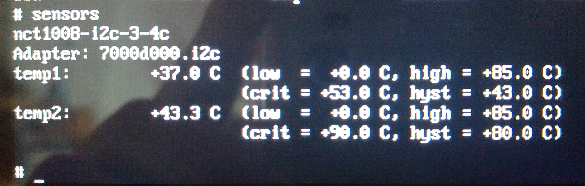
SMBus SBS
Address: 0x4C
https://www.onsemi.com/pdf/datasheet/nct1008-d.pdf
The Slave address and the ManufacturerID register do match. + This sensor is also found on Cardhu.
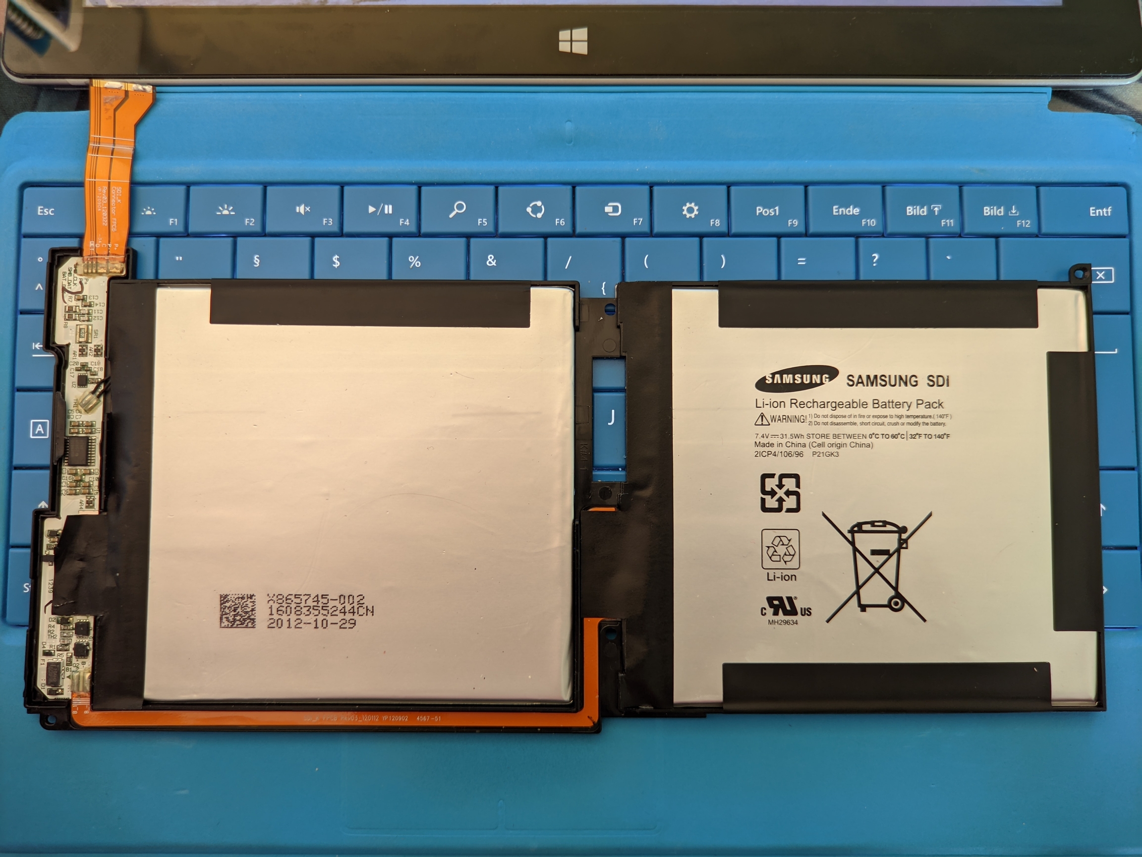
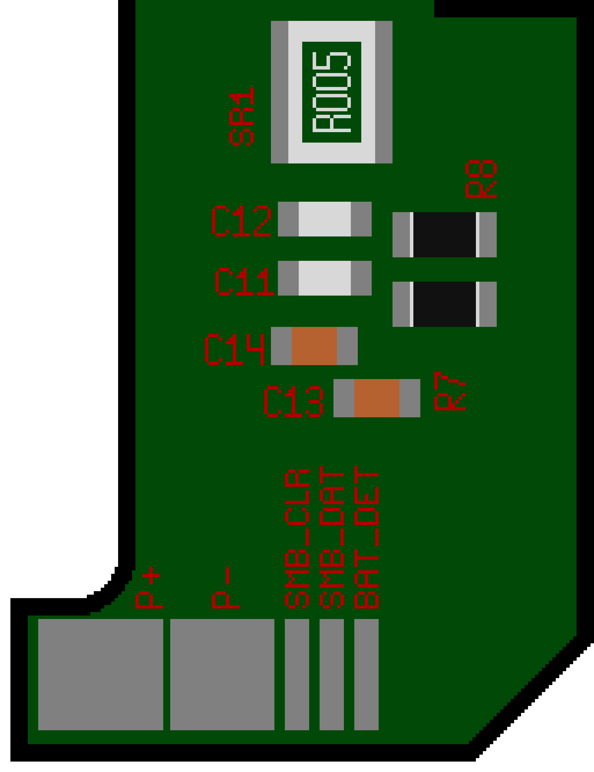
Information about the battery pack and BMS
A battery pack requires a reliable BMS. Without it you can't control and balance the cells, leading to fire hazards.
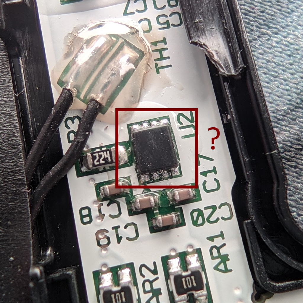
???
Specifications | Title |
Manufacturer | Samsung |
Capacity | 31.5Wh |
Voltage | 7.4V |
Model number | P21GK3 |
Technical Reference Manual
Nvidia provides a TRM (Technical Reference Manual). You can download the latetest TRM from Nvidias page here but you need to register an developer account.
https://developer.nvidia.com/embedded/tegra-3-reference
Page 20ff. Lists some Alternate pin functions. https://www.data-modul.com/sites/default/files/products/Colibri%20T30%20Tegra3%201GB_specification_12004760.pdf
https://pinout.torizon.io/ Even better information about GPIO Special functions
Inside the device is a OEM connector labeld J14 that probably served as development and debug access for components of the device.
Open your device according to this IFIXIT Guide:
https://de.ifixit.com/Teardown/Microsoft+Surface+Teardown/11275
The pads are coated with a solder mask. The solder mask can be removed carefully with a sharp object.
Be careful you don't want to cut any traces. This could damage and destroy your device! Pad size is 0.5mm
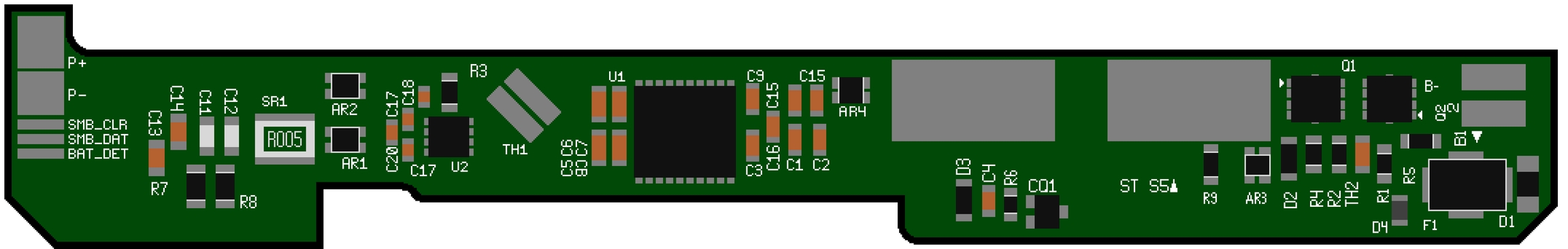
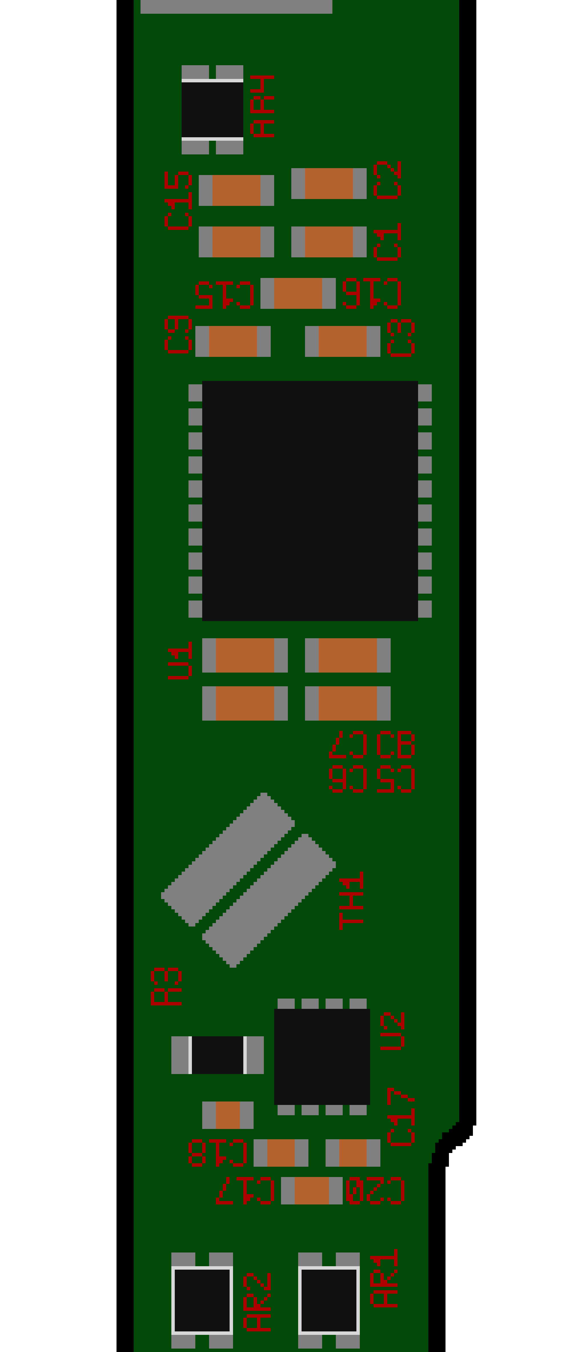
If you can identify some pins feel free to update this Schematic template
PMIC or Power Managment IC (PMIC) is an IC that contains a lot of regulators which power the CPU, Sensors and other components of Surface RT
https://www.panelook.com/LTL106AL01-002_Samsung_10.6_LCM_overview_19126.html
Many tools exist which can decode EDID.
On Ubuntu you can use edid-decode.
The ouput is below...
You can also use this EDID reader page
WIP At the we use a samsung display with same resolution and similar timings which works. But to optimize the devicetree someone has to decode EDID to panel-timings
https://elixir.bootlin.com/linux/latest/source/include/drm/drm_modes.h#L201
https://glenwing.github.io/docs/VESA-DMT-1.12.pdf page 57
Controlling the following GPIOs from UEFI Shell gave the result below. The GPIOs were extracted from ACPI
GPIO
Backlight
Logo
Note
Function
B2
Y
N
Image fades out
LVDS power down
DD0
N
Y
Logo can bee seen with
external light source
backlight power
DD2
N
N
Display is dead
panel power
H0
N
Y
PWM brightness control
PWM brightness
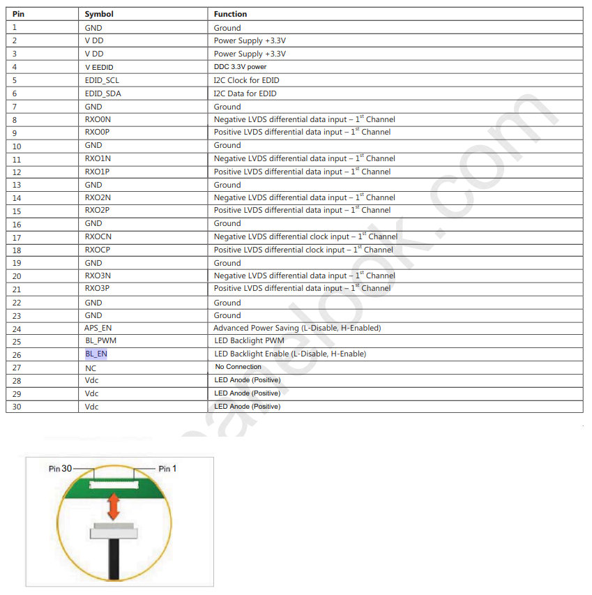
Pin
2/3 Panel VDD
GPIO DD2
25 BL_PWM
GPIO H0
26 Backlight enable
GPIO DD0
28/29/30 LED Anode
Always connected to 12V