Surface RT UART-A access
To properly debug Linux a serial console is needed. Tegra30 has 5 hardware UART ports. They are called UART-A/B/C/D/E
UART-A is on the ULPI data pins on the SoC (https://github.com/u-boot/u-boot/blob/master/arch/arm/mach-tegra/tegra30/pinmux.c#L25)
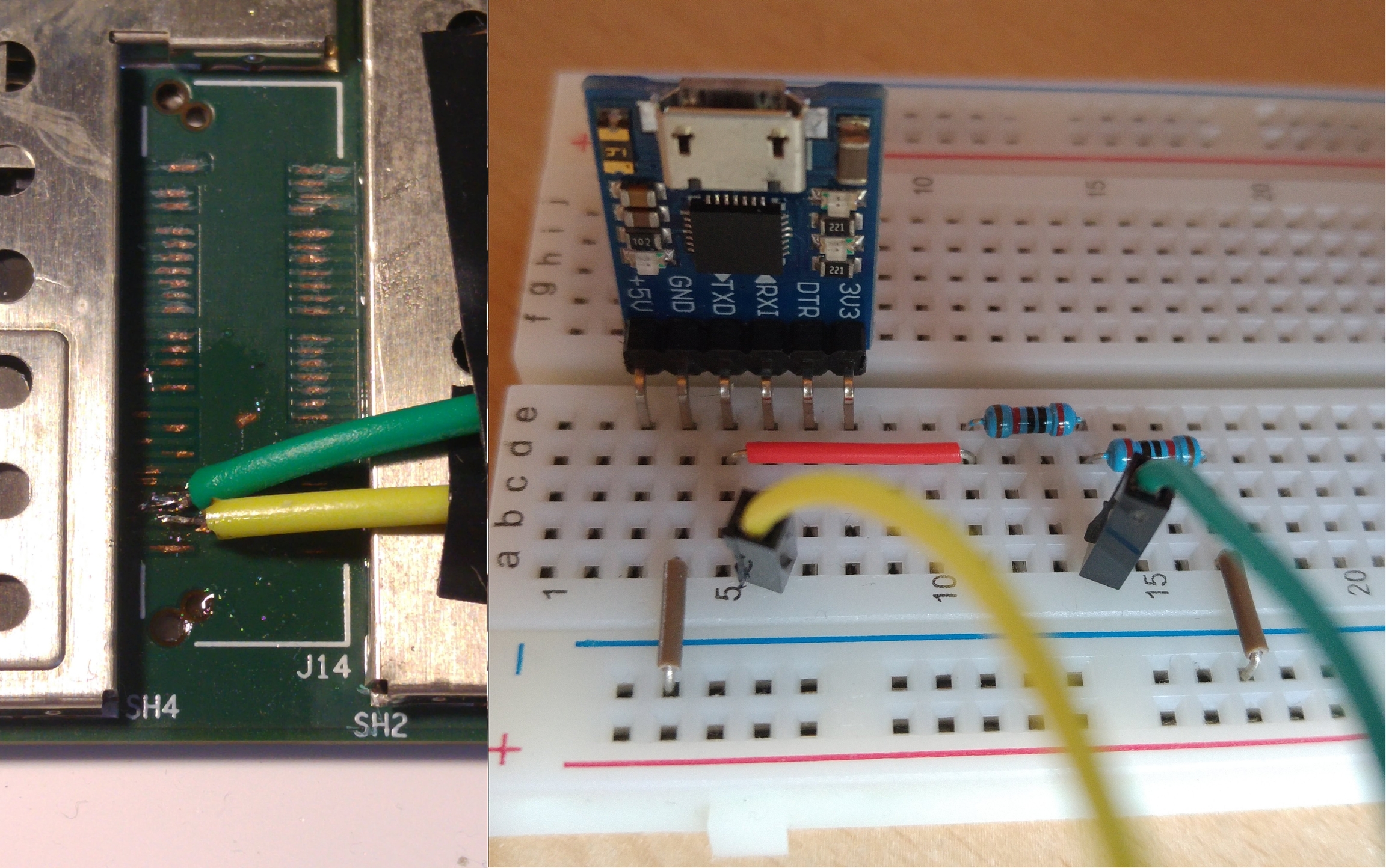
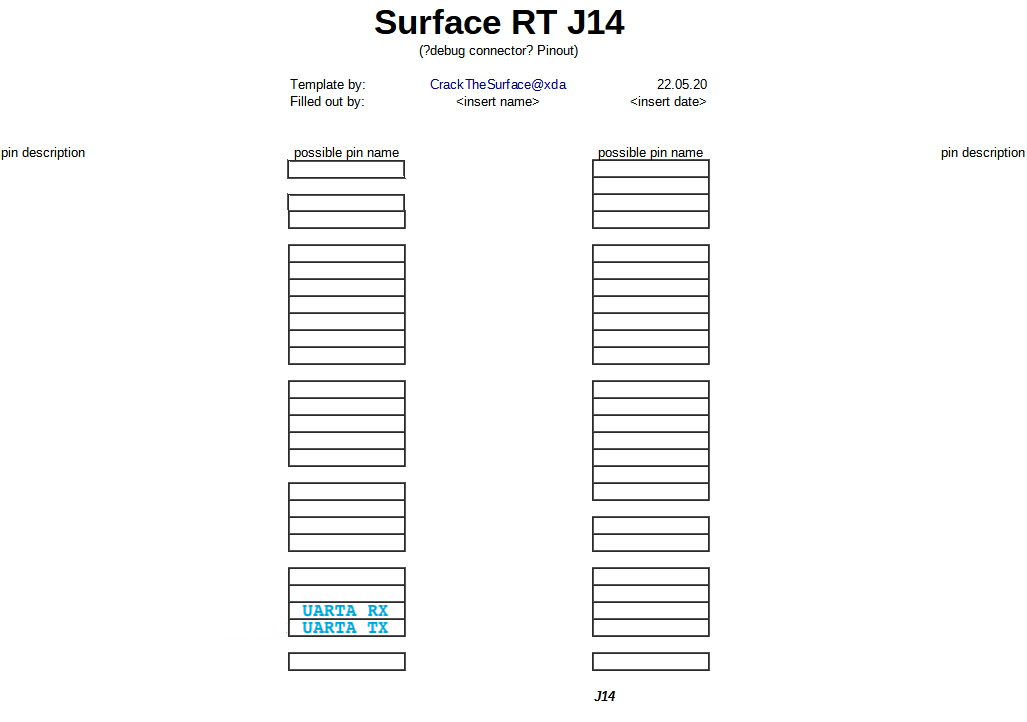
UART-A TX can be found on J14. It transmits data at 1.8V UART-A RX can be found on J14. It receives data at 1.8V
Below you can see where you can find the UARTA TX, RX pad.
GND from Surface RT must be connected to GND of your UART adapter. If you use fusee gelee your devices are connected via USB-GND. If not you must find suitable GND on sRT.
To use UART you need i.e. a usb-uart adapter, a raspberry pi, arduino, etc... A "silicon labs cp210x usb to uart bridge" was used in testing. This is a 3V3 chip which is 5V tolerant. Receiving a 1.8V signal works fine. But sending 3.3V to a 1.8V input is dangerous.
Be careful when you remove the soldermask (green layer covering the copper). You dont want to cut the trace or short it to any trace below! These pads are very tiny, soldering them is hard without skill and good equipment. It's recommened to use small solid core wire. if you use stranded wire (like i did) only use 2-3 strands. Cut off the rest. Secure your wires with good tape.
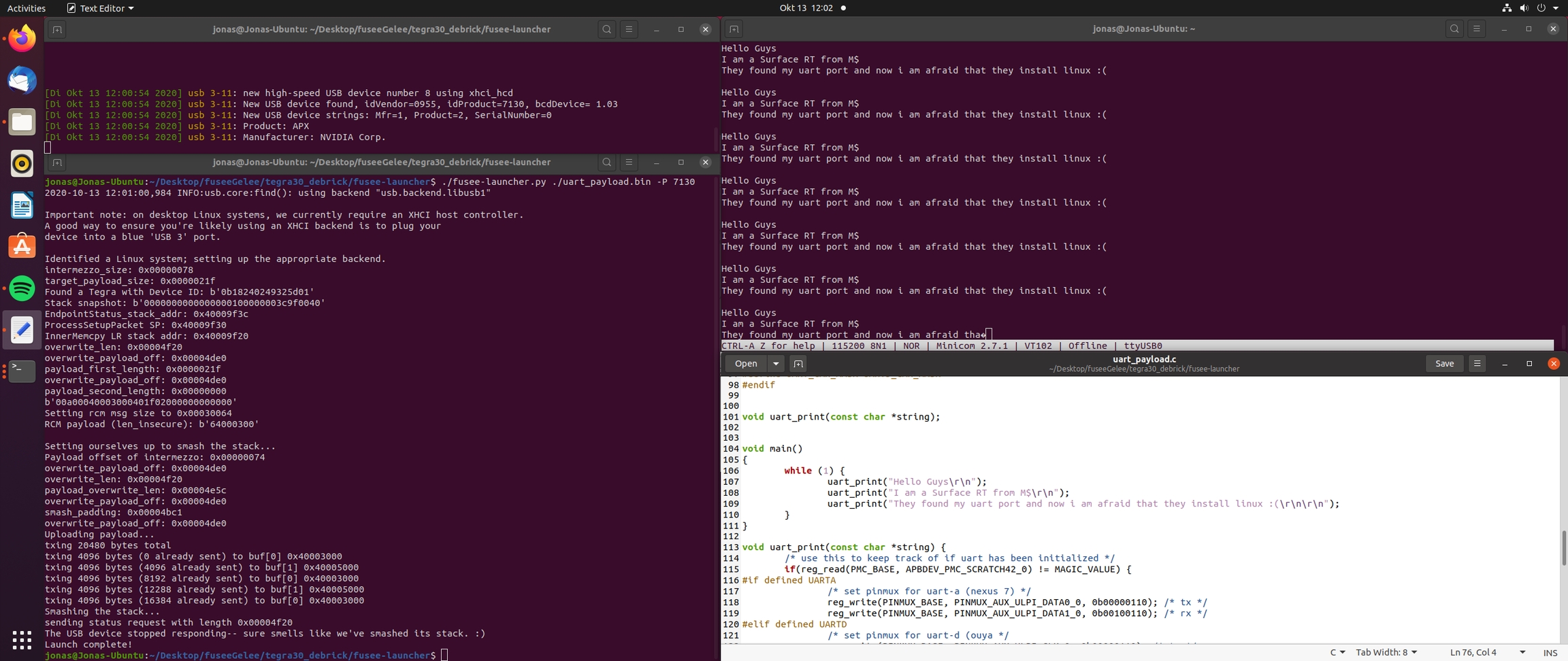
A Fusée Gelée payload which initializes UART-A with Baud: 115200, Bits: 8, Stopbits: 1, Parity:None
was used to find it.
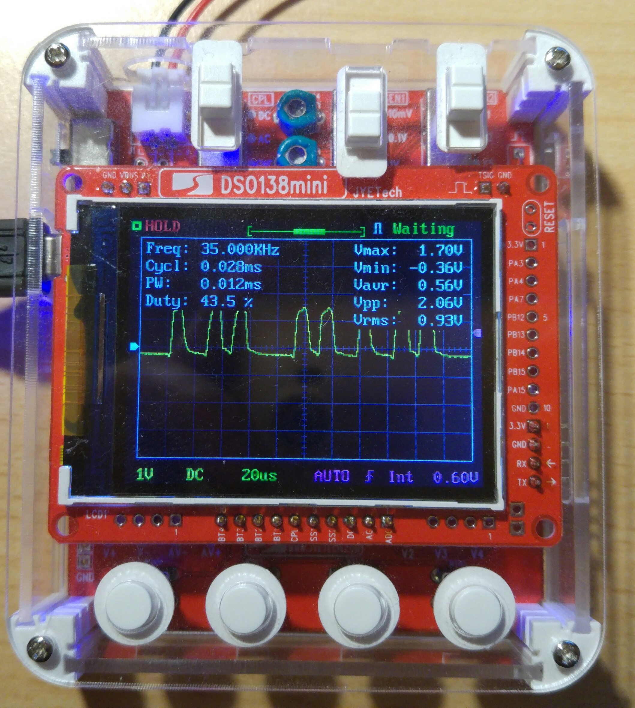
After initialisation its spams data to the transmit buffer.
We took an oscilloscope and checked that there isn't a pin which provides more than 5V (max of uart adapter).
After this we probed every pin with a usb uart adapter and minicom. After a few seconds we found the corresponding TX-pad.
Top left: dmesg -Tw show that sRT is booted in APX mode. Also shows if it gets disconnected.
Bottom left: Fusee Gelee launcher with payload and ProductID (see dmesg)
Top right: Minicom output
Bottom right: Fusee gelee payload source code
At this time we got uboot booting. We got output from uboot over UART-A-TX so we only had to bring an TX signal from pc to the RX pad on surfaceRT.
One educated guess later we found RX next to TX.
Uboot told us that 1 isn't a valid command. after this we tried help and and got a solid answer
Setup your Raspberry Pi to communicate with the SurfaceRT.
To enable the UART on your Raspberry Pi to be used as host you need to configure it:
sudo raspi-config
Go to 5 - interfacing options
Go to P6 - serial
Would you like a login shell to be accessible over serial? Answer: 'No'
Would you like the serial port hardware to be enabled? Answer: 'Yes'
Reboot your Raspberry Pi.
See Raspberry Pi for information on how to physically connect your RPI and your SRT.
To establish a UART-Connection to the Surface RT use
RPI2: minicom -b 115200 -D /dev/ttyAMA0
RPI_Zero minicom -b 115200 -D /dev/ttyS0
To escape from minicom use STRG+A and then X.
Further information: https://www.raspberrypi.org/documentation/configuration/uart.md
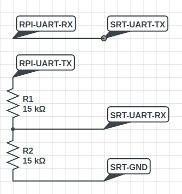
Connect 3.3/5V UART hardware to a 1.8V device using a voltage divider
We recommend buying suitable 1.8V equipment
Use a voltage divider to get TX 3.3V / 5V down to 1.8V
3.3V: Z1 = 20k; Z2 = 20k
5.0V: z1 = 20k; Z2 = 47k
These values should be safe even if the resistors vary by 5%
Test the output Voltage before you send data to 1.8V ports
Connection of Z2 to GND is very important. If it has a bad connection Vout can get close to Vin
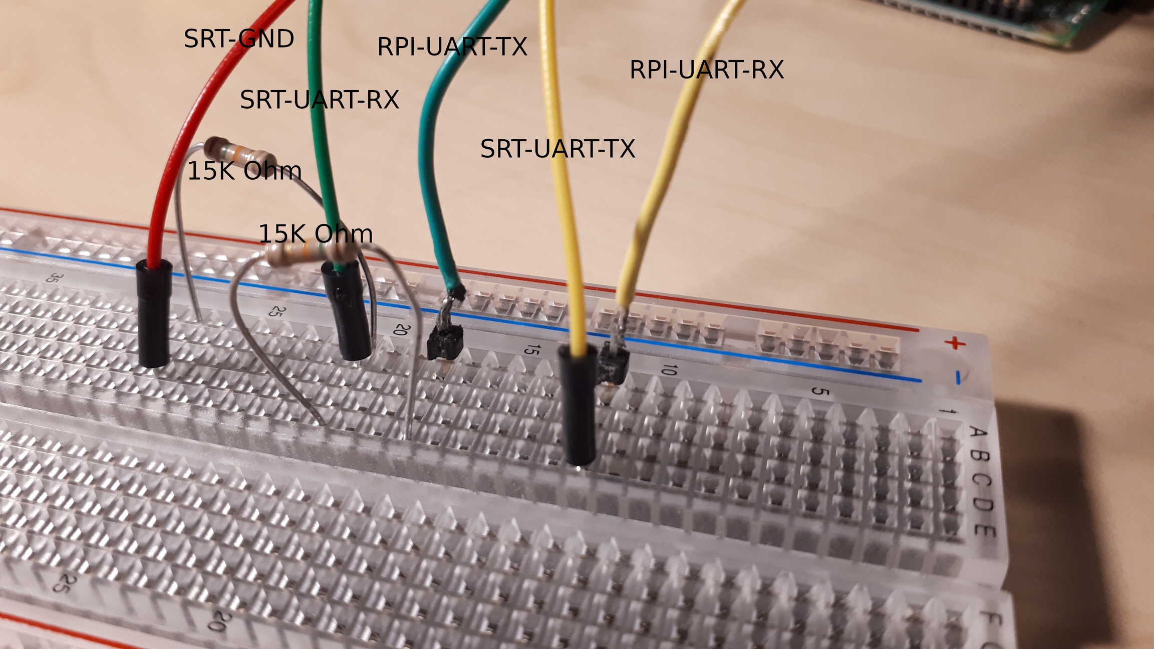
You need to have a common GND. The easiest method is connecting UART-GND and SRT-GND.
See Raspberry Pi UART Setup for further on information on how to setup your RPI.
Raspberry Pi's use 3.3V UART. Surface RT only uses 1.8V.
Raspberry Pi can receive 1.8V signals without a problem. But the Surface doesn't want to receive a 3.3V Signal. Therefore we need a levelshifter. A simple and cheap solution is to use a voltage divider, as shown above.